Guide To Heat Treating
Process automation, redefining how fastener parts are heat treated
Table of Contents
Guide To Ordering Heat Treating Services, How to Design Parts that will be Heat Treated, Steel Types Comparisons and Hardness Charts
This “How to order heat treating services guide,” or “Processing,” is a guide for plant managers, purchasing agents, part designers, account representatives and machine operators, who can benefit in knowing how to order processing based on a customer’s desired parameters in the finished metal parts. By becoming familiar with this guide you will understand the effects that heat treating has on metal parts and be more knowledgeable of a heat treat process that will meet your specifications and quality specifications for simple tool steels, or for processing that must meet certifications for ISO, Nadcap, AMS, CQI-9 and AMS-H-6875-Dept. of Defense certifications.
How to Work With a Heat Treater
A heat treater is a specialist in the processing of metals. An experienced and reputable heat treater is able to diagnosis and recommend a preferred treatment for your metal parts only if he knows everything possible about the material that he will be working with. Therefore, it is important that the parts you send to a heat treater for processing include written information with the following details:
Ordering heat treating
1. Parts Identification for Packing and Shipping
Work submitted for heat treatment should be carefully identified with appropriate packing slip or purchase order.
The number of parts for each part number or lot should be noted. Weights or similar data can be used where applicable.
2. Cad Illustrations and Drawings
All purchase orders for parts being processed the first time should include the drawings and all applicable specifications. If the drawings must be returned, note this on the PO, otherwise the drawings will be stored with your job order.
Processing information pertinent to the heat treater should be noted, such as dimensional tolerances required, allowance required for stock removal, finishing operations that follow, and additional treatments or hardness tests.
3. Material Designation
Specify the SAE or AISI material designation wherever possible.
The material trade name or purchase specification can be substituted.
For new or super alloys, include the manufacturer’s heat treating recommendations.
The use of general terms, such as “oil hardening tool steel” is incomplete information. Be more specific to prevent your metal from undergoing the wrong treatments.
You need to know if your metal was cold formed in the mill, and if it was, make sure to tell the heat treater. Ask you supplier to contact the mill, if necessary to obtain this information. Stress relieving may have to be preformed prior to the actual processing.
4. Processing Information is Critical for Quality Heat Treating
The processing your parts should be described as best as possible with information you have available. If you are not sure about a type of process, call Phoenix Heat Treating at 602-258-7751, or another competent heat treating company, for information about a process that will meet the quality standards for the finished parts. We will help you write a processing order that will prevent unwanted results.
General terms, such as “annealing,” should be more fully explained to avoid misinterpretation, especially when using a heat treating facility that is operating their equipment manually.
Case hardening treatments should specify the method of reading the case depth (effective or total case depth), and the range allowed prior to grinding. Case hardening depth needs to be specified in thousandths. Keep in mind that tighter tolerances for case depth are now achievable with heat treaters who provide automated heat treating. A “normal” case spread of ten-thousand’s can be set on automated equipment to not exceed a four-thousand’s case range. (More on this later in this outline). Thus you can be more specific on your hardening specifications.
Special operations or finishing treatments such as vapor blast, sand blast, plating, etc., should be specified.
Treatments requiring other finishing processes, such as machining, should be carefully noted.
If certified heat treating is required to meet certifications in the automotive, aerospace, military, medical, high-tech, etc., industries, a copy of the specification should accompany the work. For error-free processing and guaranteed repeatability, it’s best to send your parts to a heat treat company that operates automated processing with sensor-control technology that documents the entire process. The automated logic-control systems used by Phoenix Heat Treating provide time-stamped, electronic records that prove the process was performed to meet ISO, Nadcap, AMS and CQI-9, Department of Defense certifications, and other specifications.
5. Hardness Requirements
Hardness requirements should state the hardness test required, (Rockwell, Brinell, etc.), and range.
For tool steels, a three-point hardness range is desirable, such as “Rockwell C 60-62.” Five to six points should be allowed on hardness below Rockwell C 50.
Inspection locations should be noted. Critical areas in which hardness tests are not allowed should also be noted.
Stock removal allowed for preparing surfaces for hardness checking should be noted, if critical.
Parts requiring heat treating to a specified tensile strength should be accompanied by tensile test specimens. Conversion from tensile strength to hardness is not reliable and should be done only with your customer’s written approval.
6. Tolerance Requirements
Specify the dimensional tolerances required after heat treatment. On critical work, it is recommended that you consult with an experienced heat treater prior to ordering processing.
Finished surfaces should be carefully noted.
7. Related Information for Ordering Heat Treating
Develop a close working relationship with a heat treater who can guarantee times, temperatures and atmospheres supported with repeatable performance. Leading-edge automated heat treating eliminates the guess work involved in manually operated heat treating equipment.
Processing is a very precise service that should be considered a critical finishing step in your metal fabrication. For that reason, a reputable, certified heat treater will encourage a working relationship with you to enhance your understanding of the processes and methods used; as well as allow the heat treater to get to know your company and your company’s needs and requirements.
The heat treater will help you better understand the processing steps and soak times required, and the related delivery schedules for the particular metal processing you are requesting.
A reputable heat treater will want to know the ultimate utilization of your metal parts.
Involve Your Heat Treater Before Designing Parts
A turn-key heat treating company with an IN-HOUSE metallurgical engineer and INSPECTION LAB will provide you with critical specifications about the material your are working with. Knowing the chemistry and limitations of the material will enable you to produce higher quality parts that will not fail in service, and will allow you to provide a more informed service to your customers. A heat-treating company that offers full turn-key services will include lab service in your processing orders and will send it to third parties who are not familiar with your company.
Know the Relationship Between Part Design and Heat Treating
The heat treating industry, represented by the Metal Treating Institute, has developed an industry statement for heat treaters which recognizes that inherent problems in metal chemistry or part design can still make the job of properly heat treating a piece of metal very difficult, or impossible. Without knowing the origin of the metal and the utilization specifications, it would be risky to proceed with processing. The below information explains this more clearly.
Knowing the source of stresses acting at various times prior to heat treating, or during the heat treating cycles is three-fold:
Stress created at the mill when the material was cold formed
Stresses resulting from the mere application or removal of heat,
Stresses resulting from changes in the crystalline structures of the steel.
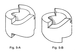
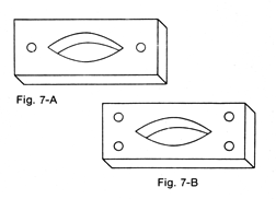
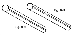
Comparisons of Improper and Proper Part Design
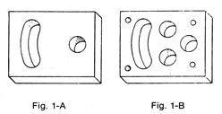
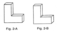
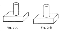
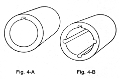
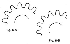
If a radius is not provided at the base of gear teeth as in Fig 6-A, each corner will become a stress concentration point that can lead to cracks. The design can be corrected by leaving generous fillets as shown in Fig 6-B.

Facts About Metal Hardness and Heat Treating
The Brinell Metal Hardness Method
| Hole DIA | Brinell Metal Hardness Number |
| Mm | 500 kg | 1000 kg | 1500 kg | 2000 kg | 2500 kg | 3000 kg |
| 3.00 | 69 | 138 | 208 | 276 | 346 | 415 |
| 3.05 | 67 | 134 | 201 | 267 | 334 | 401 |
| 3.10 | 65 | 129 | 194 | 258 | 324 | 388 |
| 3.15 | 62 | 125 | 188 | 250 | 313 | 375 |
| 4.00 | 38 | 76 | 115 | 152 | 191 | 229 |
| 4.05 | 37 | 74 | 112 | 148 | 186 | 223 |
| 4.10 | 36 | 72 | 109 | 145 | 181 | 217 |
| 4.15 | 35 | 71 | 106 | 141 | 177 | 212 |
The Brinell test is easily and quickly made, and with a little practice the impression diameter can be read accurately. It is good practice to request that your heat treater’s lab use the average of two readings of the impression diameter made at right angles to each other. Calibration of the machine should be done periodically with the use of metal test blocks of standard hardness.
The Rockwell Hardness Method
The following table shows the scale designation of some of the more commonly used combinations of penetrator and load:
| Scale Designation Penetrator Load |
| Standard Scales |
| A | Diamond | 60 kg |
| D | Diamond | 100 kg |
| C | Diamond | 150 kg |
| F | 1/16” Ball | 60 kg |
| B | 1/16” Ball | 100 kg |
| E | 1/8” Ball | 100 kg |
| 15N | Diamond | 15 kg |
| Standard Scales |
| 30N | Diamond | 30 kg |
| 45N | Diamond | 45 kg |
| 15T | 1/16” Ball | 15 kg |
| 30T | 1/16” Ball | 30 kg |
| 45T | 1/16” Ball | 45 kg |
Any porosity in the work will cause erratic readings
The surface to be tested must be smooth and clean
The surface to be tested must be square with the penetrator
The test piece must make good contact with the anvil of the machine
In uncertain situations, a serious of readings should be made
Calibration of testing machines should be done at frequent intervals using metal testing blocks
| Dial Reading | Diameter of work |
| 1/4” | 3/8” | 1/2” | 3/4” | 1” | |
| Round work correction (add) to A & C Scale Readings |
| 20 | 6.0 | 4.5 | 3.5 | 2.0 | 1.5 |
| 25 | 5.5 | 4.0 | 3.0 | 2.0 | 1.0 |
| 30 | 5.0 | 3.5 | 2.5 | 1.5 | 1.0 |
| 50 | 2.5 | 2.0 | 1.5 | 1.0 | 0.5 |
| 55 | 2.0 | 1.5 | 1.0 | 1.0 | 0.5 |
| 60 | 1.5 | 1.0 | 1.0 | 0.5 | 0.5 |
Other Hardness Tests
Microhardness testers used by Phoenix Heat Treating are a combination of microscope and penetrating unit. The penetrating unit is a diamond indenter capable of being loaded in the range of 1 to 1000 grams (1000 grams is 1 kg). The microscope is used to measure the size of the hole made by the penetrator under the applied load, and this establishes the hardness number. The Tukon and Knoop are the most widely used of this type of equipment. Microhardness testers are essentially precision laboratory devices.
Metal Hardness Conversion Tables
Tool Steel Grades and Tool Steel Symbols
Appropriate symbols are assigned to the generally accepted types of tool steels. These types, or classes of tool steels have been grouped into seven major categories and each of these has been assigned a letter symbol. The seven major groups are further subdivided in 13 basic types and 55 specific analyses.
The Seven Major Groups of Tool Steels
| Group | Symbol | Description |
| I | W | Water Hardening Tool Steels |
| II | S | Shock Resisting Tool Steels |
| III | Cold Work Tool Steels | |
| O | Oil Hardening Types | |
| A | Medium Alloy Air Hardening Types | |
| D | High Carbon, High Chromium Types | |
| IV | Hot Work Tool Steels | |
| H10-H19 | Chromium Types | |
| H21-H39 | Tungsten Types | |
| H41-H59 | Molybdenum Types | |
| V | High Speed Tool Steels | |
| M | Molybdenum Types | |
| T | Tungsten Types | |
| VI | P | Mold Steels |
| VII | Special Purpose Tool Steels | |
| L | Low alloy types | |
| F | Carbon Tungsten Types |
Example: W1 – Water Hardening straight carbon tool steel
A2 – 5% Chromium air hardening die steel
I. Water Hardening Tool Steels
Water hardening tool steels are essentially shallow hardening carbon steels in which, in some grades, chromium or vanadium is added for deeper hardening. They may be machined with standard high-speed tools and are generally used for forming, shaping, cutting, blanking, cold heading, embossing, and coining dies.
| Type or Symbol | Identifying Elements % |
| C | Cr | V | |
| W1 | .60/1.40 | – | – |
| W2 | .60/1.40 | – | .25 |
| W5 | 1.10 | .50 | – |
II. Shock Resisting Tool Steels
This group consists primarily of the chrome-tungsten and the silicon-manganese types. They have relatively low carbon (.40/.60) and are essentially high strength steels with excellent impact properties and sufficient wear resistance for their intended applications. They have good machinability, and the tungsten types develop enough red hardness for hot heading applications. Other primary applications are for master hobs, chisels, cold impact applications or any application where resistance to shock is of primary importance.
| Type or Symbol | Identifying Elements % |
| C | Mn | Si | W | Mo | Cr | |
| S1 | .50 | – | – | 2.50 | – | 1.50 |
| S2 | .50 | – | 1.00 | – | .50 | – |
| S5 | 55 | .80 | 2.00 | – | .40 | – |
| S7 | .50 | – | – | – | 1.40 | 3.25 |
III. Cold Work Tool Steels, Oil Hardening Tool Steel Types
These are general-purpose grades with carbon content about 90%. Additions of manganese, chromium, tungsten, and sometimes molybdenum permit oil quenching. Machinability approaches that of the water hardening (W) steels. Typical applications are for cold shearing, forming, shaping, and cold blanking dies.
| Type or Symbol | Identifying Elements % |
| C | Mn | Si | W | Mo | Cr | |
| 01 | .90 | 1.00 | – | .50 | – | .50 |
| 02 | .90 | 1.60 | – | – | – | – |
| *06 | 1.45 | – | 1.00 | – | .25 | – |
| 07 | 1.20 | – | – | 1.75 | – | .75 |
Medium Alloy Air Hardening Tool Steel Types
Use of higher chromium, molybdenum, and manganese make these steels air hardening and increase resistance to wear. Air hardening minimizes distortion and size change during heat treating.
| Type or Symbol | Identifying Elements % |
| C | Mn | Si | W | Mo | Cr | V | Ni | |
| A2 | 1.00 | – | – | – | 1.00 | 5.00 | – | – |
| A3 | 1.25 | – | – | – | 1.00 | 5.00 | 1.00 | – |
| A4 | 1.00 | 2.00 | – | – | 1.00 | 1.00 | – | – |
| A6 | .70 | 2.00 | – | – | 1.00 | 1.00 | – | – |
| A7 | 2.25 | – | – | **1.00 | 1.00 | 5.25 | 4.75 | – |
| A8 | .55 | – | – | 1.25 | 1.25 | 5.00 | – | – |
| A9 | .50 | – | – | – | 1.40 | 5.00 | 1.00 | 1.50 |
| ***A10 | 1.35 | 1.80 | 1.25 | – | 1.50 | – | – | 1.80 |
High Carbon, High Chromium Tool Steel Types
These steels, with the combined 12% chromium and higher carbon content, provide superior performance for long run die applications. All analyses in this class exhibit low distortion in heat treatment, have deep hardening characteristics, very high wear resistance, and good resistance to softening at elevated temperatures. They are more difficult to machine and after hardening must be ground with extreme care to prevent surface grinding checks.
| Type or Symbol | Identifying Elements % |
| C | Mo | Cr | V | Co | |
| D2 | 1.50 | 1.00 | 12.00 | 1.00 | – |
| D3 | 2.25 | – | 12.00 | – | – |
| D4 | 2.25 | 1.00 | 12.00 | – | – |
| D5 | 1.50 | 1.00 | 12.00 | – | 3.00 |
| D7 | 2.35 | 1.00 | 12.00 | 4.00 | – |
IV. Hot Work Tool Steels, Chromium Types
Types H11, H12, and H13 are most commonly used for hot work applications. These steels are deep hardening and exhibit excellent strength and toughness at elevated temperatures, together with good resistance to heat checking. They have good machinability in the annealed state. Typical applications are forging dies and inserts, die casting and extrusion dies as well as plastic molding dies. They are normally referred to as the 5% chromium group with additions of tungsten, molybdenum, and vanadium. H11 is now commonly used as an ultra high strength aircraft structure material.
| Type or Symbol | Identifying Elements % |
| C | W | Mo | Cr | V | Co | |
| H10 | .40 | – | 2.50 | 3.25 | .40. | – |
| H11 | .35 | – | 1.50 | 5.00 | .40 | – |
| H12 | .35 | 1.50 | 1.50 | 5.00 | .40 | – |
| H13 | .35 | – | 1.50 | 5.00 | – | – |
| H14 | .40 | 5.00 | – | 5.00 | – | – |
| H19 | .40 | 4.25 | – | 4.25 | 2.00 | 4.25 |
This group of tool steels has relatively low carbon content (.30/.40) with 9 to 18% tungsten as the primary alloying element, with additional chromium. As might be expected, these grades have very high red hardness properties. They are deep hardening and exhibit high wear resistance. Normal applications are for hot forging dies and extrusion press tooling. They are difficult to machine.
| Type or Symbol | Identifying Elements % |
| C | W | Cr | V | |
| H21 | .35 | 9.00 | 3.50 | – |
| H22 | .35 | 11.00 | 2.00 | – |
| H23 | .30 | 12.00 | 12.00 | – |
| H24 | .45 | 15.00 | 3.00 | – |
| H25 | .25 | 15.00 | 4.00 | – |
| H26 | .50 | 18.00 | 4.00 | 1.00 |
These grades have carbon content of 0.60% with molybdenum as the primary alloying element, plus chromium, vanadium, and some tungsten. The fairly high carbon and alloy content provides good wear resistance together with high red hardness and resistance to heat checking.
| Type or Symbol | Identifying Elements % |
| C | W | Mo | Cr | V | |
| H41 | .65 | 1.50 | 8.00 | 4.00 | 1.00 |
| H42 | .60 | 6.00 | 5.00 | 4.00 | 2.00 |
| H43 | .55 | – | 8.00 | 4.00 | 2.00 |
V. High Speed Tool Steels
Symbol M.
These grades use from 5% to 9% of molybdenum as a substitute for tungsten in other high speed steels in order to reduce the cost. Cobalt is used in some grades to improve red hardness. These steels are used in cutting tools such as drills, reamers, taps, and milling cutters.
| Type or Symbol | Identifying Elements % |
| C | W | Mo | Cr | V | Co | |
| M1 | .80 | 1.50 | 8.00 | 4.00 | 1.00 | – |
| M2 | .85 | 6.00 | 5.00 | 4.00 | 2.00 | – |
| M3 CI.1 | 1.05 | 6.00 | 5.00 | 4.00 | 2.40 | – |
| M3 CI.2 | 1.20 | 6.00 | 5.00 | 4.00 | 3.00 | – |
| M4 | 1.30 | 5.50 | 4.50 | 4.00 | 4.00 | – |
| M6 | .80 | 4.00 | 5.00 | 4.00 | 1.50 | 12.00 |
| M7 | 1.00 | 1.75 | 8.75 | 4.00 | 2.00 | – |
| M10 | .90 | – | 8.00 | 4.00 | 2.00 | – |
| M30 | .80 | 2.00 | 8.00 | 4.00 | 1.25 | 5.00 |
| M33 | .90 | 1.50 | 1.50 | 4.00 | 1.15 | 8.00 |
| M34 | .90 | 2.00 | 8.00 | 4.00 | 2.00 | 8.00 |
| M36 | .80 | 6.00 | 5.00 | 4.00 | 2.00 | 8.00 |
Tungsten Tool Steel Types
The steel that is most characteristic of this group is T1, commonly referred to as 18-4-1, the respective percentages of tungsten, chromium and vanadium. Some grades contain cobalt which increases the red hardness. The usual applications are in the field of cutting tools such as drills, reamers, broaches, etc. and for high production punches where a combination of high compressive strength, wear resistance and toughness is required. In some cold heading operations the cobalt grades are used when red hardness is sufficiently important.
| Type or Symbol | Identifying Elements % |
| C | W | Cr | V | Co | |
| T1 | .70 | 18.00 | 4.00 | 1.00 | – |
| T2 | .80 | 18.00 | 4.00 | 2.00 | – |
| T4 | .75 | 18.00 | 4.00 | 1.00 | 5.00 |
| T5 | .80 | 18.00 | 4.00 | 2.00 | 8.00 |
| T6 | .80 | 20.00 | 4.50 | 1.50 | 12.00 |
| T8 | .75 | 14.00 | 4.00 | 2.00 | 5.00 |
| T15 | 1.50 | 12.00 | 4.00 | 5.00 | 5.00 |
VI. Mold Steel Types
These Grades may be referred to as cold hobbing steels, but are more normally used for machined cavity dies. They are low in carbon and after machining or hobbing are carburized to develop good wear resistance. Grade P20 is a higher carbon type and may be heat treated before machining and used without further treatment.
| Type or Symbol | Identifying Elements % |
| C | Mo | Cr | Ni | Al | |
| P2 | .07 | .20 | 2.00 | .50 | – |
| P3 | .10 | – | .60 | 1.25 | – |
| P4 | .07 | .75 | 5.00 | – | – |
| P5 | .10 | – | 2.25 | – | – |
| P6 | .10 | – | 1.50 | 3.50 | – |
| P10 | .35 | .40 | 1.25 | – | – |
| P21 | .20 | – | – | 4.00 | 1.20 |
VII. Special Purpose Tool Steels, Low Alloy Tool Steel Types
This is a group of high carbon cold work steels similar to the W steels, but containing various amounts of alloy for increased wear resistance and hardenability. They are essentially oil hardening.
| Type or Symbol | Identifying Elements % |
| C | Mn | Mo | Cr | V | Ni | |
| L2 | .50/1.10 | – | – | 1.00 | .20 | – |
| L3 | 1.00 | – | – | 1.50 | .20 | – |
| L6 | – | – | .25 | .75 | – | 1.50 |
| *L7 | 1.00 | .35 | .40 | 1.40 | – | – |
Symbol F.
These grades are commonly referred to as “finishing” steels. The combination of high carbon and tungsten content develops extremely hard surfaces for deep drawing dies and for sharp cutting edges on finishing tools. They are not red-hard.
| Type or Symbol | Identifying Elements % |
| C | W | Cr | |
| F1 | 1.00 | 1.25 | – |
| F2 | 1.25 | 3.50 | – |
| F3 | 1.25 | 3.50 | .75 |
The Five Types of Heat Treating Processes
Stresses Relief
Modification of cold worked material
Development of physical properties in solid solution alloys
Change in surface composition
Development of special characteristics
1. Relief of Stresses in Metals
Severe cold working such as rolling, spinning, bending or drawing, creates high internal stresses in metal due to disrupting the crystalline structure. These stresses are undesirable for most types of service, and result in loss of strength, distortion, reduced part longevity, or even complete failure, such as breakage. Stresses can be relieved without internal structure change and with no metal softening by a simple low temperature heat treatment. Cold worked steel parts can be stress relieved at 400°F to 800°F. Severely cold worked parts, such as tightly coiled or sharply bent wire products, can be improved by this treatment.
Uneven heating and cooling will set up internal stresses in metal. Heating always causes an increase in volume in the area being heated, the normal increase being uniform in all directions. The shrinkage that results from cooling is also typically uniform in all directions. If a part is heated non-uniformly, the expansion of the heated part is restricted where it joins the unheated part, and since a volume change must occur, the heated section is actually forced out of its designed shape. The shrinkage upon cooling will not pull the part back into its original shape and therefore there a considerable stress is created where the two sections join. Welding can cause this sequence of events and the resulting stresses can be very significant. Similarly, when a uniformly heated part is cooled unevenly, the faster cooling section pulls the softer, hot section out of shape and stresses are set up when the hot section cools. This occurs when castings are broken out of a mold, and particularly when castings contain sections of different thickness, or while quenching a piece with widely varying thicknesses and dimensions.
Relief of shrinkage stress is accomplished by heating to a temperature where the yield strength is lowered to allow the stresses to expend themselves. In steels, heating to about 1200°F, and holding for a pre-determined length of time (depending on the complexity of the part), is usually sufficient to completely eliminate shrinkage stress, without change of internal structure. Cooling from a stress relieving treatment can be better managed through process automation where the cool-down times and temperatures can be infinitely controlled to prevent shrinkage stress from reoccurring. For more information on automated processing, call 602-258-7751, Phoenix Heat Treating.
2. Modification of Cold Worked Metals
Heating a cold worked material to cause re-crystallization restores ductility, lowers hardness, and permits further working without danger of breaking. Heating to a temperature higher than required for recrystallization causes undesirable grain growth, which can cause an “orange peel surface” on further working. The temperature required for re-crystallization is a function of the amount of work applied prior to heating and is lower for the more severely worked parts. When grain size and hardness are critical, the heat treating should be performed on automated processing equipment to eliminate the guesswork involved with manually operated production equipment.
3. Physical Properties in Solid Solution Metal Alloys
The ability of a solvent to dissolve other materials is a function of the temperature of the mixture. Thus in a saturated solution of ordinary salt in water (brine) at room temperature, the water cannot dissolve any more salt no matter how much salt is added to the mixture. However, if the temperature is raised, more of the salt will go into solution to a new saturation point. Cooling from the higher temperature back to room temperature causes the rejection of salt from the solution, exactly as much as was dissolved during the heating process. The heating process has caused the dispersion of some solid salt into minutely-sized particles in the solution, and the subsequent cooling has induced some of the very finely-dispersed particles to join together into much larger pieces. Heating is a dissolving process; cooling is a precipitation process.
Many solid solutions behave in a manner similar to the behavior of brine. In the solid solution, the atoms are free to travel, and when the material is heated, atoms break away from larger particles and go on their way, in solution, as individual atoms. During cooling, the individual atoms collect into larger pieces and form a precipitate. Atoms in a solution have a strong tendency to become uniformly distributed.
The travel of atoms requires time, and any solid solution alloy can be made uniform in composition by simply giving time at temperature. On the other hand, the collecting of atoms during precipitation also requires time. This opens up the possibility of developing control over precipitation by controlling the time available during cooling. Thus it is possible to actually prevent precipitation in many alloys by simply cooling so fast that no time for precipitation is available. The process of rapid cooling to retain at room temperature a solution which normally would decompose by precipitation is called a “solution treatment.”
The solution that is retained at room temperature as a result of solution treatment is unstable and has a tendency to decompose by precipitation. In some alloys, precipitation will occur in time at room temperature, in others it can be implemented by mild reheating. In either case, the process of precipitation is called “aging”; self-aging at room temperature and artificial aging at higher temperature. The size of the precipitated particles is a function of the aging temperature, becoming larger at higher temperatures. Each solution treated alloy has an optimum aging temperature for developing best mechanical properties, but for certain requirements it may be desirable to age at a higher temperature, called “overaging”.
Heating a solution-treated alloy above a normal aging temperature results in deterioration of properties and should be avoided. For example, welding of a solution-treated alloy will result in greatly reducing the strength in the area of the weld due to gross over-aging. The only remedy is to follow the welding with a re-solution treatment and aging.
Steels form a group of solid-solution alloys whose heating and cooling patterns are modified by an allotropic change in iron. Iron is a body-centered cubic material (alpha) up to 1670° F., and is face centered cubic (gamma) above 1670° F. Gamma iron will dissolve a substantial amount of carbon, while alpha iron will dissolve practically no carbon.
Since steels are essentially alloys of iron with carbon, the iron-carbon solubility curve will give considerable information about changes that occur when steels are heated and cooled. It will therefore be of help in understanding what can be accomplished in various heat treating processes.
The Difference Between Ferrite And Austenite Steels
In a sense the names ferrite and austenite are family names; every member of the family of solutions that has the host lattice of face-centered cubic iron is called austenite. The same with ferrite. Common usage extends the definitions to include the metal iron with no dissolved material. Thus low temperature iron is called ferrite, and about 1670° F, it is called austenite.
Process Automation
There have been significant changes in processing equipment and methods in the last few years that you should be familiar with before ordering your next heat treating job. Manually operated, mechanical equipment is being phased out and replaced with fully automated processing. The days of plant managers carrying around index cards in shirt pockets with an accumulation of heat treat recipes written on them are quickly coming to an end (because too many heat treating formulas have been lost in the wash). Today’s leading-edge automation uses Programmable Logic Controllers (PLC’s), and microprocessor-based stand-alone loop controllers that are designed to synchronize the flow of inputs, sensors and contacts – from various field devices – to specific outputs, valves, flow meters, motors and contacts. In other words, expensive manual labor and the use of index cards are becoming archaic in this industry.
With automation, the coordination of inputs and outputs leads to precisely timed actions that permit tight control of even the most stringent processing applications. This efficiency reduces operating costs and skilled-labor overhead for the heat treater, and delivers a precisely defined and documented process for the customer. The beauty in automated technology is that your heat treating jobs can be duplicated a thousand times with no deviation in the processing. And, the processing data is recorded in real, and can be printed out and presented as a guarantee that the processing was performed to your exact specifications. This is certainly a value-added service you can provide to your customers.
About Phoenix Heat Treating
For more information on Phoenix Heat Treating, call Peter Hushek, company president, at 602-258-7751. Or, email Peter via our contact page
Information contained in this Heat Treating Guide was provided courtesy of the Metal Treating Institute (MTI), and Phoenix Heat Treating, Inc.
© Copyright 2010. No part of this document can be reproduced or copied for publication or distribution without permission. It is intended for personal use by company production departments only.
